
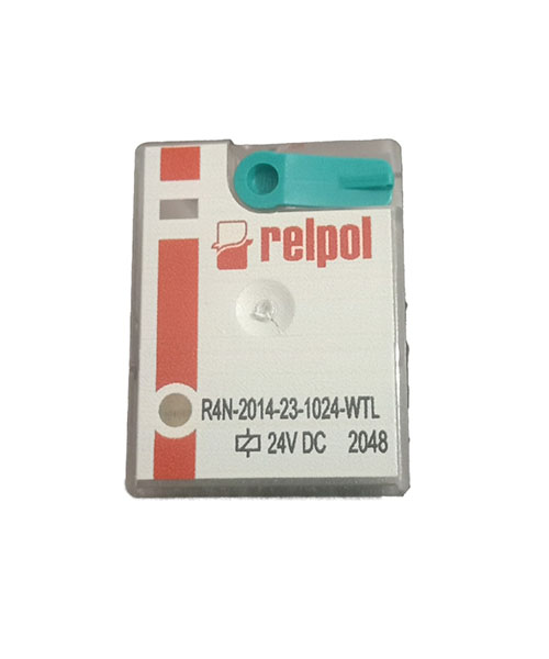
R4 Series Plug In Power Relays for general applications
All relays are designed for mounting in plug-in sockets with WTL features as standard (W – mechanical indicator + T – lockable front test button)
• Compact size
• Relays of general application
• Cadmium – free contacts
• AC and DC coils
• For plug-in sockets, 35 mm rail mount or on panel mounting *
• WT (mechanical indicator + lockable front test button) – standard features of relays for plug-in sockets.
Relays may be provided with the test buttons (no latching) and plugs
| Models | R2 | R3 | R4 |
| Number and type of contacts | DPDT | 3PDT | 4PDT |
| Contact material | AgNi** | AgNi** | AgNi** |
| Rated / max. switching voltage AC | 250 V / 440 V | 250 V / 440 V | 250 V / 250 V |
| Min. switching voltage | 10 V | 10 V | 10 V |
| AC1 | 12 A / 250 V AC | 10 A / 250 V AC | 6 A / 250 V AC |
| AC15 | 3 A / 120 V; 1.5 A / 240 V (B300) | 3 A / 120 V; 1.5 A / 240 V (B300) | 1.5 A / 120 V; 0.75 A / 240 V (C300) |
| AC3 | 370 W (single-phase motor) | 370 W (single-phase motor) | 125 W (single-phase motor) |
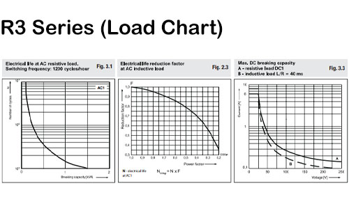
| DC1 | 12 A / 24 V DC (see Fig. 3.1) | 10 A / 24 V DC (see Fig. 3.2) | 6 A / 24 V DC (see Fig. 3.3) |
| DC13 | 0.22 A / 120 V; 0.1 A / 250 V (R300) | 0.22 A / 120 V; 0.1 A / 250 V (R300) | 0.22 A / 120 V; 0.1 A / 250 V (R300) |
| Min. switching current | 5 mA | 5 mA | 5 mA |
| Max. inrush current | 24 A | 20 A | 12A |
| Rated current | 12 A | 10 A | 6A |
| Max. breaking capacity | |||
| AC1 | 3000 VA | 2500 VA | 1500 VA |
| Min. breaking capacity | 0.3 W | 0.3 W | 0.3 W |
| Contact resistance | 100 m | 100 m | 100 m |
Max. operating frequency
|
|||
| AC1 | 1200 cycles/hour | 1200 cycles/hour | 1200 cycles/hour |
| 18000 cycles/hour | 18000 cycles/hour | 18000 cycles/hour |
| Rated voltage 50/60 Hz AC DC | 6 … 240 V | 6 … 240 V | 6 … 240 V |
| 5 … 220 V | 5 … 220 V | 5 … 220 V | |
| Must release voltage | AC: 0.2 Un; DC: 0.1 Un | AC: 0.2 Un; DC: 0.1 Un | AC: 0.2 Un; DC: 0.1 Un |
| Operating range of supply voltage | see page 54 | see page 54 | see page 54 |
| Rated power consumption AC DC | 1.6 VA | 1.6 VA | 1.6 VA |
| 0.9 W | 0.9 W | 0.9 W |
| Insulation rated voltage | 250 V AC | 250 V AC | 250 V AC |
| Rated surge voltage | 4000 V 1.2 / 50 µs | with AC coils: 2500 V 1.2 / 50 µs with DC coils:4000 V 1.2 / 50 µs | 2500 V 1.2 / 50 µs |
| Overvoltage category | III | III | II |
| Insulation pollution degree | 3 | 3 | 2 |
Dielectric strength
|
2500 V AC type of insulation: basic 1500 V AC type of clearance: micro-disco. |
2500 V AC type of insulation: basic 1500 V AC type of clearance: micro-disco. |
2500 V AC type of insulation: basic 1500 V AC type of clearance: micro-disco. |
Contact – coil distance
|
2.5 mm | 2.5 mm | 1.6 mm |
|
4 mm | 4 mm | 3.2 mm |
| Operating / release time (typical) | AC: 10 ms / 8 ms; DC: 13 ms / 3 ms | AC: 10 ms / 8 ms; DC: 13 ms / 3 ms | AC: 10 ms / 8 ms; DC: 13 ms / 3 ms |
Electrical life
|
> 105; 12 A. 250 V AC see Fig. 2.1 | > 105; 10 A. 250 V AC see Fig. 2.2 | > 105; 6 A. 250 V AC see Fig. 2.3 |
| Mechanical life (cycles) | > 2 x 10⁷ | > 2 x 10⁷ | > 2 x 10⁷ |
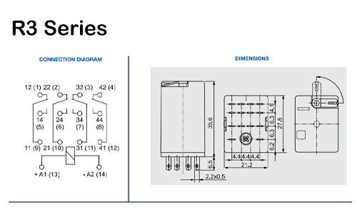
| Dimensions (L x W x H) | 27.5 x 21.2 x 35.6 mm | 27.5 x 21.2 x 35.6 mm | 27.5 x 21.2 x 35.6 mm |
| Weight | 35 g | 35 g | 35 g |
Ambient temperature
|
-40…+85 °C | -40…+85 °C | -40…+85 °C |
| AC: -40…+55 °C; DC: -40…+70 °C | AC: -40…+55 °C; DC: -40…+70 °C | AC: -40…+55 °C; DC: -40…+70 °C | |
| Cover protection category | IP 40 PN-EN 60529 | IP 40 PN-EN 60529 | IP 40 PN-EN 60529 |
| Environmental protection | RTI PN-EN 116000-3 | RTI PN-EN 116000-3 | RTI PN-EN 116000-3 |
| Shock resistance (NO/NC) | 10 g / 5 g | 10 g / 5 g | 10 g / 5 g |
| Vibration resistance | 5 g 10…150 Hz | 5 g 10…150 Hz | 5 g 10…150 Hz |
| Solder bath temperature | max. 270 °C | – | max. 270 °C |
| Soldering time | max. 5 s | – | max. 5 s |
| Models | R2 | R3 | R4 |
| Number and type of contacts | DPDT | 3PDT | 4PDT |
| Contact material | AgNi** | AgNi** | AgNi** |
| Rated / max. switching voltage AC | 250 V / 440 V | 250 V / 440 V | 250 V / 250 V |
| Min. switching voltage | 10 V | 10 V | 10 V |
| AC1 | 12 A / 250 V AC | 10 A / 250 V AC | 6 A / 250 V AC |
| AC15 | 3 A / 120 V; 1.5 A / 240 V (B300) | 3 A / 120 V; 1.5 A / 240 V (B300) | 1.5 A / 120 V; 0.75 A / 240 V (C300) |
| AC3 | 370 W (single-phase motor) | 370 W (single-phase motor) | 125 W (single-phase motor) |
| DC1 | 12 A / 24 V DC (see Fig. 3.1) | 10 A / 24 V DC (see Fig. 3.2) | 6 A / 24 V DC (see Fig. 3.3) |
| DC13 | 0.22 A / 120 V; 0.1 A / 250 V (R300) | 0.22 A / 120 V; 0.1 A / 250 V (R300) | 0.22 A / 120 V; 0.1 A / 250 V (R300) |
| Min. switching current | 5 mA | 5 mA | 5 mA |
| Max. inrush current | 24 A | 20 A | 12A |
| Rated current | 12 A | 10 A | 6A |
| Max. breaking capacity | |||
| AC1 | 3000 VA | 2500 VA | 1500 VA |
| Min. breaking capacity | 0.3 W | 0.3 W | 0.3 W |
| Contact resistance | 100 m | 100 m | 100 m |
Max. operating frequency
|
|||
| AC1 | 1200 cycles/hour | 1200 cycles/hour | 1200 cycles/hour |
| 18000 cycles/hour | 18000 cycles/hour | 18000 cycles/hour |
| Rated voltage 50/60 Hz AC DC | 6 … 240 V | 6 … 240 V | 6 … 240 V |
| 5 … 220 V | 5 … 220 V | 5 … 220 V | |
| Must release voltage | AC: 0.2 Un; DC: 0.1 Un | AC: 0.2 Un; DC: 0.1 Un | AC: 0.2 Un; DC: 0.1 Un |
| Operating range of supply voltage | see page 54 | see page 54 | see page 54 |
| Rated power consumption AC DC | 1.6 VA | 1.6 VA | 1.6 VA |
| 0.9 W | 0.9 W | 0.9 W |
| Insulation rated voltage | 250 V AC | 250 V AC | 250 V AC |
| Rated surge voltage | 4000 V 1.2 / 50 µs | with AC coils: 2500 V 1.2 / 50 µs with DC coils:4000 V 1.2 / 50 µs | 2500 V 1.2 / 50 µs |
| Overvoltage category | III | III | II |
| Insulation pollution degree | 3 | 3 | 2 |
Dielectric strength
|
2500 V AC type of insulation: basic 1500 V AC type of clearance: micro-disco. | 2500 V AC type of insulation: basic 1500 V AC type of clearance: micro-disco. | 2500 V AC type of insulation: basic 1500 V AC type of clearance: micro-disco. |
Contact – coil distance
|
2.5 mm | 2.5 mm | 1.6 mm |
|
4 mm | 4 mm | 3.2 mm |
| Operating / release time (typical) | AC: 10 ms / 8 ms; DC: 13 ms / 3 ms | AC: 10 ms / 8 ms; DC: 13 ms / 3 ms | AC: 10 ms / 8 ms; DC: 13 ms / 3 ms |
Electrical life
|
> 105; 12 A. 250 V AC see Fig. 2.1 | > 105; 10 A. 250 V AC see Fig. 2.2 | > 105; 6 A. 250 V AC see Fig. 2.3 |
| Mechanical life (cycles) | > 2 x 10⁷ | > 2 x 10⁷ | > 2 x 10⁷ |
| Dimensions (L x W x H) | 27.5 x 21.2 x 35.6 mm | 27.5 x 21.2 x 35.6 mm | 27.5 x 21.2 x 35.6 mm |
| Weight | 35 g | 35 g | 35 g |
Ambient temperature
|
-40…+85 °C | -40…+85 °C | -40…+85 °C |
| AC: -40…+55 °C; DC: -40…+70 °C | AC: -40…+55 °C; DC: -40…+70 °C | AC: -40…+55 °C; DC: -40…+70 °C | |
| Cover protection category | IP 40 PN-EN 60529 | IP 40 PN-EN 60529 | IP 40 PN-EN 60529 |
| Environmental protection | RTI PN-EN 116000-3 | RTI PN-EN 116000-3 | RTI PN-EN 116000-3 |
| Shock resistance (NO/NC) | 10 g / 5 g | 10 g / 5 g | 10 g / 5 g |
| Vibration resistance | 5 g 10…150 Hz | 5 g 10…150 Hz | 5 g 10…150 Hz |
| Solder bath temperature | max. 270 °C | – | max. 270 °C |
| Soldering time | max. 5 s | – | max. 5 s |
| Models | R2 | R3 | R4 |
| Number and type of contacts | DPDT | 3PDT | 4PDT |
| Contact material | AgNi** | AgNi** | AgNi** |
| Rated / max. switching voltage AC | 250 V / 440 V | 250 V / 440 V | 250 V / 250 V |
| Min. switching voltage | 10 V | 10 V | 10 V |
| AC1 | 12 A / 250 V AC | 10 A / 250 V AC | 6 A / 250 V AC |
| AC15 | 3 A / 120 V; 1.5 A / 240 V (B300) | 3 A / 120 V; 1.5 A / 240 V (B300) | 1.5 A / 120 V; 0.75 A / 240 V (C300) |
| AC3 | 370 W (single-phase motor) | 370 W (single-phase motor) | 125 W (single-phase motor) |
| DC1 | 12 A / 24 V DC (see Fig. 3.1) | 10 A / 24 V DC (see Fig. 3.2) | 6 A / 24 V DC (see Fig. 3.3) |
| DC13 | 0.22 A / 120 V; 0.1 A / 250 V (R300) | 0.22 A / 120 V; 0.1 A / 250 V (R300) | 0.22 A / 120 V; 0.1 A / 250 V (R300) |
| Min. switching current | 5 mA | 5 mA | 5 mA |
| Max. inrush current | 24 A | 20 A | 12A |
| Rated current | 12 A | 10 A | 6A |
| Max. breaking capacity | |||
| AC1 | 3000 VA | 2500 VA | 1500 VA |
| Min. breaking capacity | 0.3 W | 0.3 W | 0.3 W |
| Contact resistance | 100 m | 100 m | 100 m |
Max. operating frequency
|
|||
| AC1 | 1200 cycles/hour | 1200 cycles/hour | 1200 cycles/hour |
| 18000 cycles/hour | 18000 cycles/hour | 18000 cycles/hour |
| Rated voltage 50/60 Hz AC DC | 6 … 240 V | 6 … 240 V | 6 … 240 V |
| 5 … 220 V | 5 … 220 V | 5 … 220 V | |
| Must release voltage | AC: 0.2 Un; DC: 0.1 Un | AC: 0.2 Un; DC: 0.1 Un | AC: 0.2 Un; DC: 0.1 Un |
| Operating range of supply voltage | see page 54 | see page 54 | see page 54 |
| Rated power consumption AC DC | 1.6 VA | 1.6 VA | 1.6 VA |
| 0.9 W | 0.9 W | 0.9 W |
| Insulation rated voltage | 250 V AC | 250 V AC | 250 V AC |
| Rated surge voltage | 4000 V 1.2 / 50 µs | with AC coils: 2500 V 1.2 / 50 µs with DC coils:4000 V 1.2 / 50 µs | 2500 V 1.2 / 50 µs |
| Overvoltage category | III | III | II |
| Insulation pollution degree | 3 | 3 | 2 |
Dielectric strength
|
2500 V AC type of insulation: basic 1500 V AC type of clearance: micro-disco. |
2500 V AC type of insulation: basic 1500 V AC type of clearance: micro-disco. |
2500 V AC type of insulation: basic 1500 V AC type of clearance: micro-disco. |
Contact – coil distance
|
2.5 mm | 2.5 mm | 1.6 mm |
|
4 mm | 4 mm | 3.2 mm |
| Operating / release time (typical) | AC: 10 ms / 8 ms; DC: 13 ms / 3 ms | AC: 10 ms / 8 ms; DC: 13 ms / 3 ms | AC: 10 ms / 8 ms; DC: 13 ms / 3 ms |
Electrical life
|
> 105; 12 A. 250 V AC see Fig. 2.1 | > 105; 10 A. 250 V AC see Fig. 2.2 | > 105; 6 A. 250 V AC see Fig. 2.3 |
| Mechanical life (cycles) | > 2 x 10⁷ | > 2 x 10⁷ | > 2 x 10⁷ |
| Dimensions (L x W x H) | 27.5 x 21.2 x 35.6 mm | 27.5 x 21.2 x 35.6 mm | 27.5 x 21.2 x 35.6 mm |
| Weight | 35 g | 35 g | 35 g |
Ambient temperature
|
-40…+85 °C | -40…+85 °C | -40…+85 °C |
| AC: -40…+55 °C; DC: -40…+70 °C | AC: -40…+55 °C; DC: -40…+70 °C | AC: -40…+55 °C; DC: -40…+70 °C | |
| Cover protection category | IP 40 PN-EN 60529 | IP 40 PN-EN 60529 | IP 40 PN-EN 60529 |
| Environmental protection | RTI PN-EN 116000-3 | RTI PN-EN 116000-3 | RTI PN-EN 116000-3 |
| Shock resistance (NO/NC) | 10 g / 5 g | 10 g / 5 g | 10 g / 5 g |
| Vibration resistance | 5 g 10…150 Hz | 5 g 10…150 Hz | 5 g 10…150 Hz |
| Solder bath temperature | max. 270 °C | – | max. 270 °C |
| Soldering time | max. 5 s | – | max. 5 s |


 No products in the cart.